How to Maintain a Gas Tankless Water Heater
Comments Off on How to Maintain a Gas Tankless Water HeaterGas tankless water heaters offer an energy-efficient and cost-effective way to get hot water on demand. However, these systems require proper maintenance to prevent premature component failure and ensure long service life. Generally, tankless water heaters should be serviced once a year; however, they may require more frequent maintenance if you have hard water or if you keep your water temperature high. To ensure that your tankless water heater is properly maintained, there are many steps you can take.
What is a Tankless Water Heater?
Tankless water heaters are a type of on-demand water heater that provides hot water when needed. They are capable of heating water without the need for a storage tank. Once a hot water faucet is turned on, cold water moves through the unit’s heat exchanger before it is heated by a natural gas burner. This results in a constant supply of hot water without having to wait for a storage tank to fill.
Some of the primary advantages of gas tankless water heaters are their energy efficiency and compact size. This means that these systems not only save money but also save on the amount of space they take up in an area. However, minerals can build up within the heat exchanger over time, which can cause clogs and affect the water flow speed. Because of this, tankless water heaters require a certain degree of maintenance to ensure optimal performance. 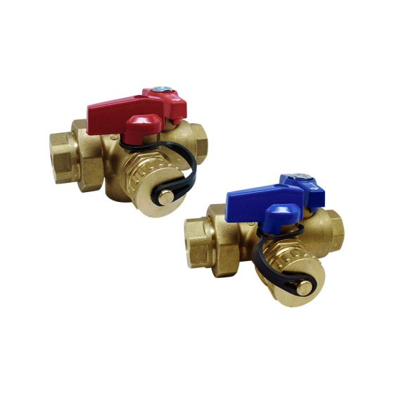
Steps for Maintaining a Tankless Water Heater
When performing maintenance on your gas tankless water heater, it’s important to follow these steps:
All tankless water heaters are not alike and therefore, cleaning procedures may differ. Always refer to the manufacturer’s recommendations on proper cleaning procedures.

1. Turn Off The Energy Source
To ensure optimal safety, it is crucial to turn off the energy source before performing inspection or maintenance. In the case of a gas tankless water heater, you will need to turn off the main gas supply valve.
2. Close All Main Water Valves
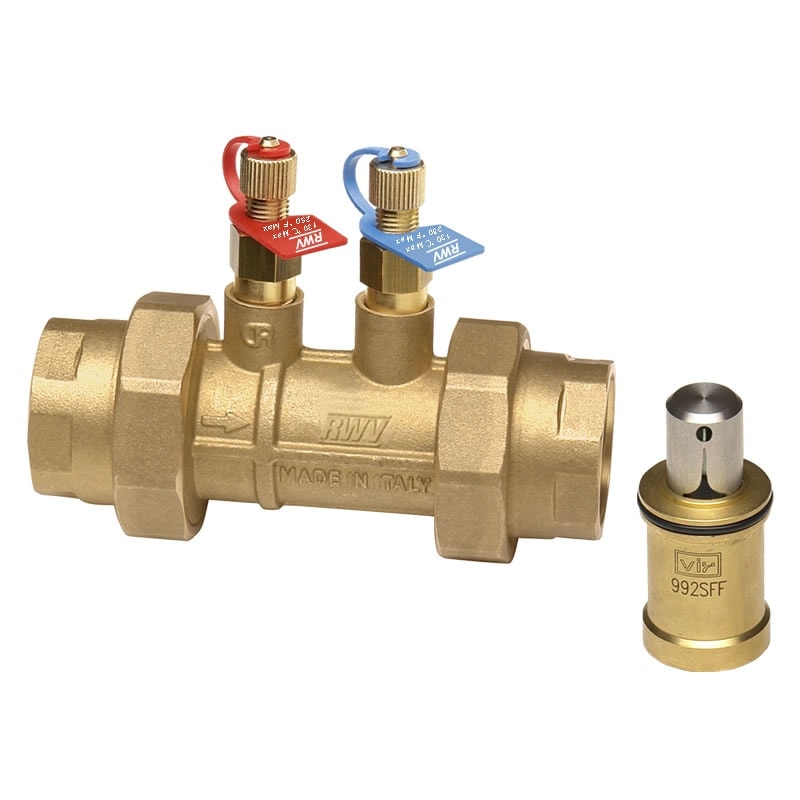
To prevent water from entering the water heater, you must close the main water valves. Typically, there is a blue valve that marks cold water (in) and a red valve that marks hot water (out).
3. Remove Purge Port Valve Caps
Purge port valve caps cover and protect the hose connections used for maintenance.
4. Attach Hoses To Each Valve
Connect hoses to the hot and cold purge ports. The hose connected to the cold valve (blue) will attach to a small recirculation pump. The hose connected to the hot valve (red) will feed back to the cleaning solution container.
5. Open the Port Valves
Open all the port valves by turning them perpendicular to the direction of the water lines.
6. Descale
To thoroughly clean your tankless water heater, use a commercial descaling solution or white vinegar mixture to the container. The recirculation pump should be submerged in the cleaning fluid container. Turn on the pump. The pump will push the cleaning fluid through the hose and into the heat exchanger. The fluid will then exit the heater and return to the cleaning fluid container.
(Note: some manufacturers require the electrical power to be on during this procedure to allow all internal actuated valves to open properly)
7. Flush and Drain the Unit
To complete your maintenance routine, simply flush and drain your tankless water heater for approximately 45-60 minutes for thorough cleaning. Now, you can close the port valves, disconnect the hosing, and reseal the purge valves. It is always a good idea to do a final flush with clean water to remove any cleaning solution from the unit.
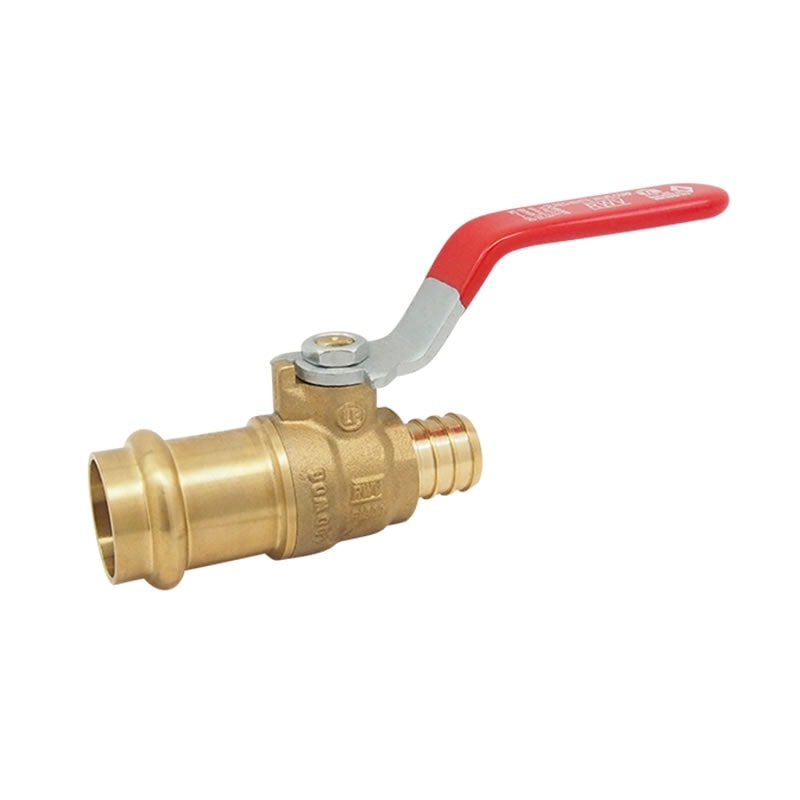
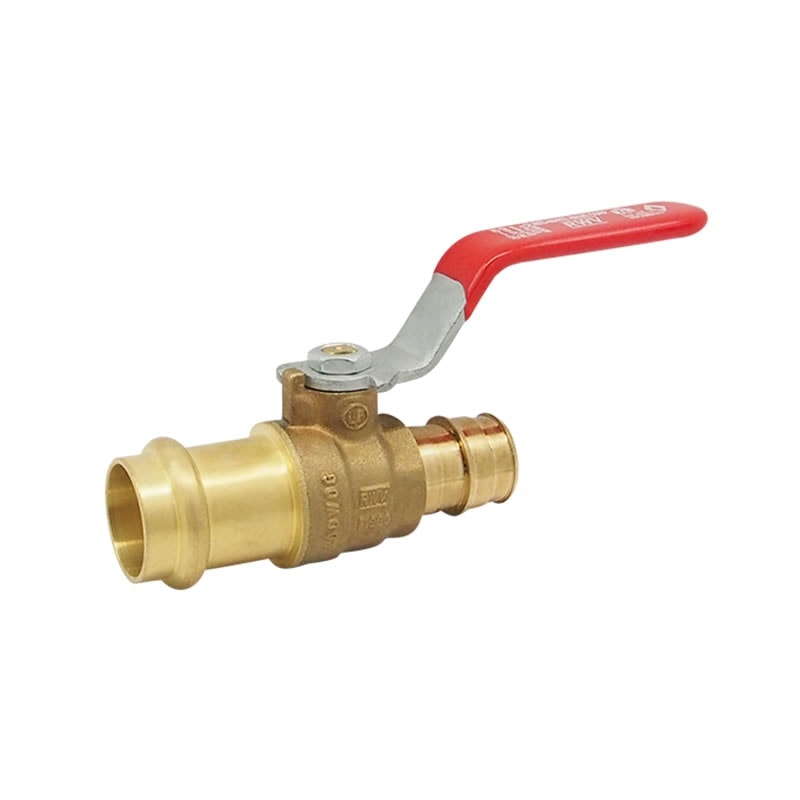
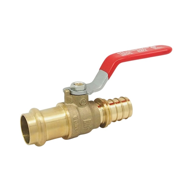
Tankless Water Heater Valve Kits From RED-WHITE VALVE CORP.
At RED-WHITE VALVE CORP., we offer valve and valve kits for gas tankless water heater maintenance. To ensure that all your daily tasks run smoothly, it’s crucial to maintain proper water pressure, and maintaining your water heater’s pressure relief valves is a key step in doing this. Our water heater relief valves relieve excess pressure in your tankless water heater to prevent pressure buildup that could lead to a tank burst.
Our valve and valve kits for tankless water heater maintenance include:
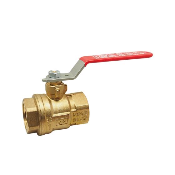
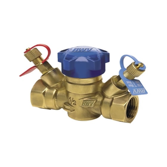
- 3420RAB/TAB LF Tankless Water Heater Valve Kit. This valve kit features virgin PTFE seats, an integral base drain, a purge port V/Cap, and an integral relief valve.
- 350R/352R Tankless Contractor Kit with Gas Accessories. The 350R/352R kit includes 3400RAB or 3420RAB configurations, a gas valve, and a flexible gas connector.
- 3400AB LF Tankless Water Heater Valve Kit. This tankless water heater valve kit features a full port, virgin PTFE seats, integral base drain, purge port with cap, and an integral relief valve.
To learn more about the gas tankless water heater maintenance solutions from RED-WHITE VALVE CORP., contact us or request a quote today.