What is a Gas Ball Valve?
Comments Off on What is a Gas Ball Valve?Valves come in a wide array of types to control the flow of liquids and gases within a system. Industries rely on numerous valves in applications ranging from chemical process systems to plumbing, with some of the most common valve types including:
- Ball valves
- Butterfly valves
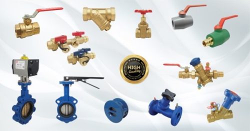 Check valves
- Diaphragm valves
- Gate valves
- Globe valves
- Knife gate valves
- Parallel slide valves
- Pinch valves
- Piston valves
- Plug valves
- Sluice valves
In their most general process and piping system applications, the above valves may perform numerous functions, such as starting or stopping material flows, regulating system flow and pressure, throttling flow, controlling flow direction, and relieving excess pressure to keep systems operating within safe levels.
Ball valves are ideal for controlling the flow of liquid or gas through a system. The rotary ball within the valve stops the flow of material when the valve reaches a specific state. Ball valves perform well in low-flow situations, throttling vapors and gases in hydrocarbon processing applications. Various applications rely on the low torque and tight seal of ball valves to start and stop the flow of gases and liquids.
This blog will discuss the advantages, disadvantages, and most common uses and applications for gas ball valves.
 What Makes Gas Ball Valves Different?
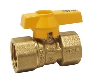
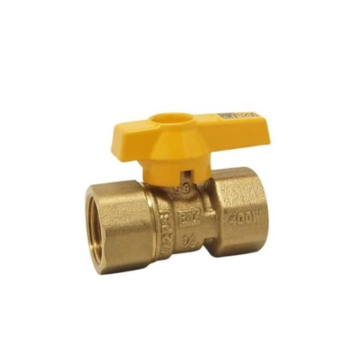
Gas ball valves deliver better performance than other valve types in many applications. Gas ball valves offer a lightweight and compact alternative to heavy brass gas valves. These ball valves come in a range of configurations to suit various specifications and can deliver ideal performance in hydrocarbon systems, as well as vapor, air, and gas systems.
Most gas ball valves are quarter-turn for easy operation and seal tightly due to the rotating ball mechanism. The valve can start and stop the flow of various liquids and offers a bubble-tight seal when closed. Ball valves often provide an ideal solution for connecting other instruments using tubing.
Many high-temperature and high-pressure applications rely on metal-seated ball valves to deliver dependable performance. Gas ball valves close and open quickly, providing impressive control of high-pressure flows.
The Advantages and Disadvantages of Gas Ball Valves
Ball valves offer a range of benefits for industrial gas system applications, with few drawbacks. The advantages of choosing a ball valve include:
- Versatility – Performs in a broad range of industrial applications
- Efficiency – Works at low torque with a bubble-tight seal
- Ease-of-use – The lightweight and compact design removes frustration from use and installation
- Affordability – Lower cost than valves of a similar rating
- Simple maintenance – Reliable operation and easy to repair
- Strength – Dependable performance in high-temperature, high-pressure, and high-volume applications
- Durability – Robust operation with a long service life
Gas ball valves can be at a disadvantage in high-velocity flow and throttling applications. These applications can speed up valve erosion and cause early failure. Using the improper ball valve for the specific fluid may also contribute to faster wear. There are a wide range of ball valves available to suit a variety of unique applications.
Gas Ball Valve Uses/Applications
Gas ball valves offer reliable performance in combustible gas applications and effectively regulate air, gas, and vapor flows. Residential and commercial properties rely on gas ball valves to deliver liquefied petroleum gas (LPG), natural gas, manufactured gas, and gas/air mixtures to gas equipment and appliances. Gas appliances such as boilers, water heaters, furnaces, fireplaces, and gas stoves also commonly rely on a ball valve.
Gas Ball Valves From RED-WHITE VALVE CORP.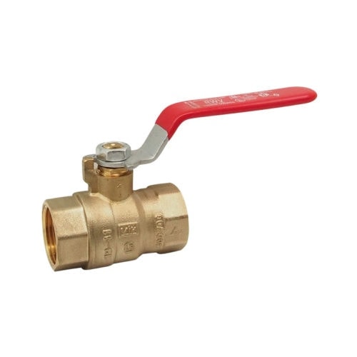

Offering airtight seals and enough durability to provide years of reliable flow control, gas ball valves provide an ideal solution for an expansive range of applications. Ball valves are simple to install and affordable, with a broad selection of material and design options. RED-WHITE VALVE CORP. gas ball valves are made to high standards and 100% air-tested to ensure optimal performance when regulating material flows.
RED-WHITE VALVE CORP. has been serving the international market with industrial valves since 1971. We ensure the highest quality by manufacturing all of our valves in-house and We maintain multiple warehouses throughout North America giving us unsurpassed fill rates to our family of wholesalers. Browse our line of ball valves to find the best valve for your application, or contact us today with any questions or concerns.
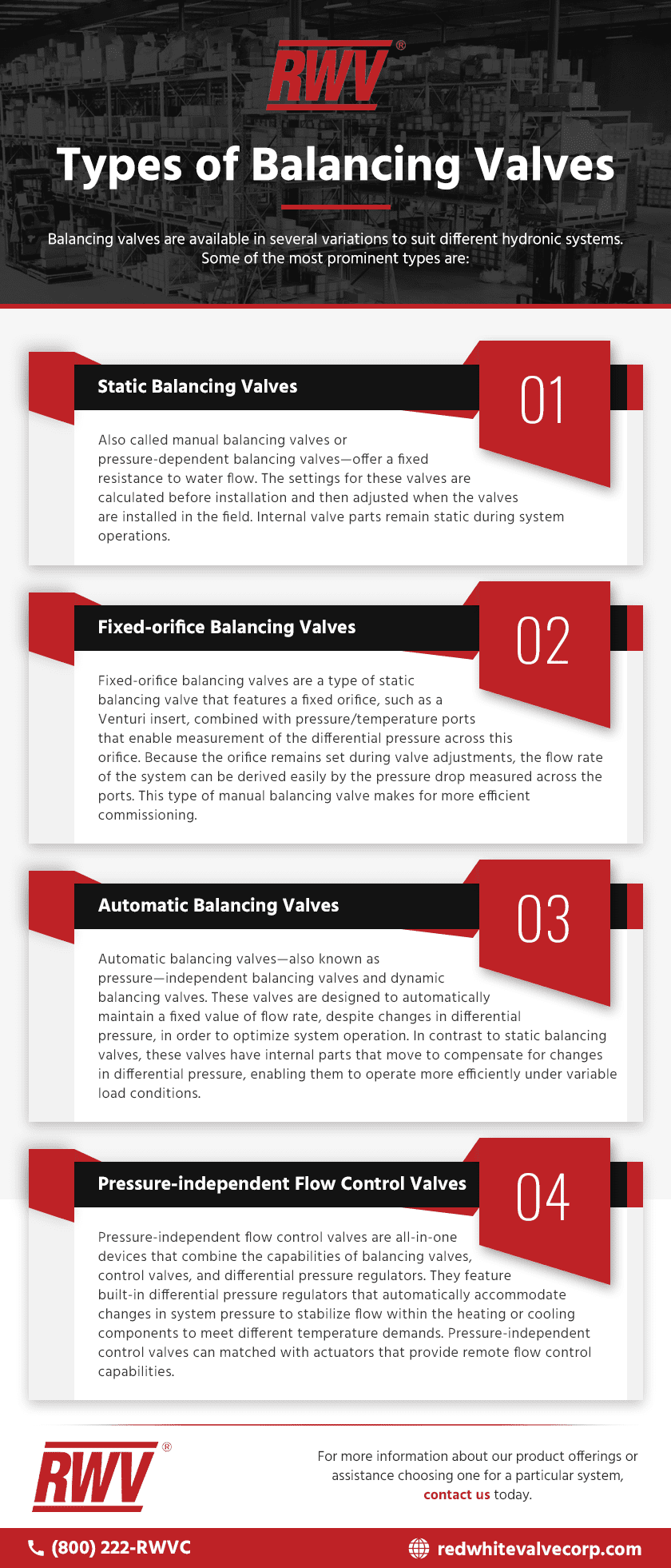
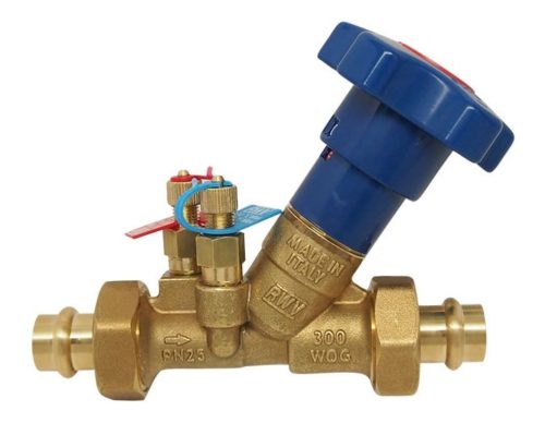 Hydronic systems are HVAC systems that utilize water to heat and cool different areas of a facility.Balancing valves are valves designed to attain hydraulic balance within such systems by regulating fluid flow and pressure. When selected and installed properly, they equalize system pressure, creating comfortable thermal conditions in the building while optimizing energy and operating costs.